|
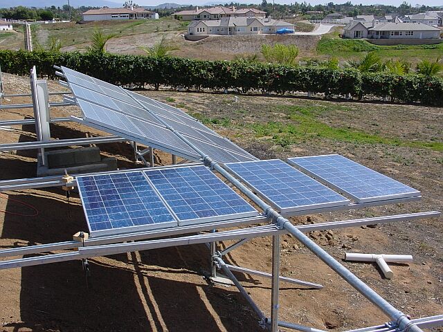
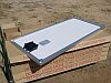
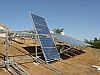
Each bay of the structure accommodates four
PV panels mounted on a pair of struts that have
been clamped to the rolling axle. For the Kyocera KC-120 panels,
the optimum strut spacing is 55-3/8" measured between outside
edges. The axle clamps are left loose to permit fine adjustment and
alignment as the panels are being attached.
|
 |
|
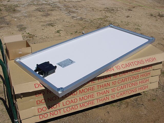
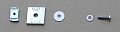
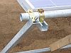
The mounting hardware is installed on each panel before
placement on the struts. The 1/4"-20 x 1" bolt and the
washers are 316 stainless steel. The channel nut and square
platform washer are galvanized steel. Using stainless components
in contact with the aluminum PV panel frame resolves concerns about
dissimilar metal corrosion, although this is not a likely problem
in our dry climate.
|
|
|
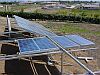
With the struts clamped horizontal, the panels are set in their approximate
positions. The
channel nuts drop into the channel and the assembly can be moved and
aligned in the track.
The best alignment procedure I found was to make several passes
tightening the bolts finger tight while wiggling the channels to index
the channel nuts. I used some extra square platform washers as
temporary spacers to maintain a small space between panels. After
several iterations, the entire frame becomes magically square and
aligned. Then the bolts can be tightened to the final torque.
Next is a visual warp check is made with corrections as required. Then
the two loose axle clamps are tightened.
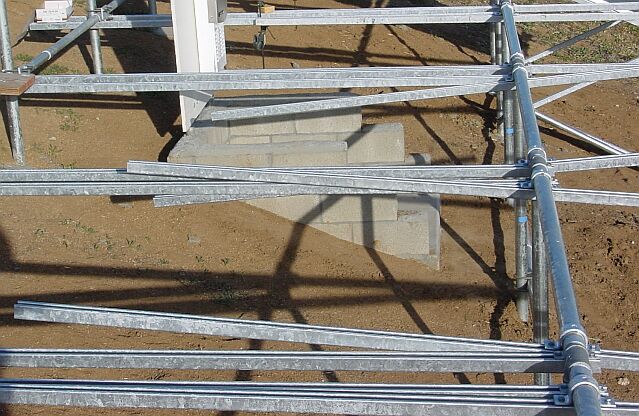
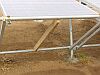
With the frame still held horizontal, a length of 1-1/2" pipe
is clamped to the south end. This pipe will provide an attachment
for the elevation adjustment braces.
|
 |
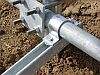 |
The frame is rotated into position for attaching the
elevation braces. A 1-1/2" fender washer is sandwiched between the pipe strap and brace at the lower
joint. This allows the joint to rotate freely.
|
|
|
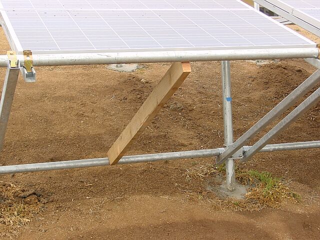
Finally, with assistance from a calibrated 2
x 4, the completed frame is fastened at the desired angle. Future
adjustments are made by loosening the upper pipe straps, moving the frame to
rest on a calibrated 2 x 4 for the desired angle, and retightening the
straps.
|
 |
|
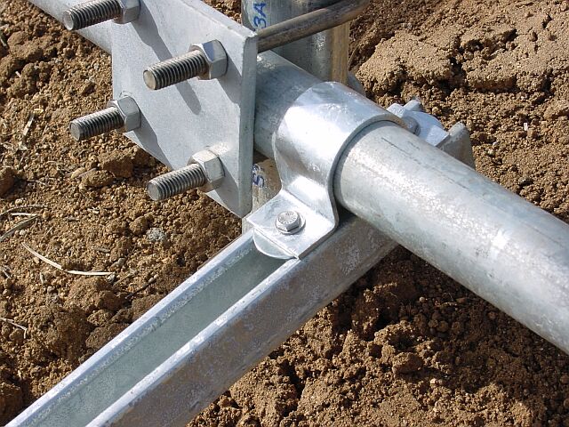
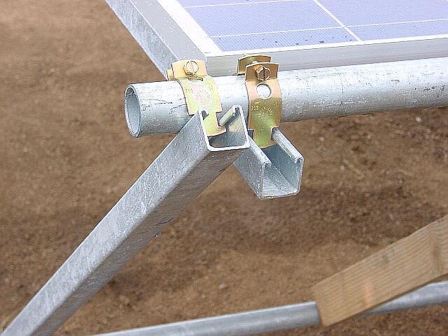
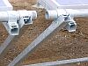
Two styles of connection hardware are available; a lightweight "pipe clamp"
and a heavy duty "pipe strap". The pipe clamp is
probably adequate for this job and is inexpensive (130 lbs axial force
and about $0.50). The heavy duty pipe strap, my preference, provides a much stronger
joint and costs a lot more (about 800 lbs axial force and about $2.25
with the additional hardware needed).
For the 2" pipe connections that hold the frame
struts to the rolling axle, I recommend the stronger
pipe strap.
|
Pipe Clamp
Pipe Strap
|