|
Site Information
Latitude: 33.343 deg. N
Longitude: 117.233 deg. W
Winter solstice noon elevation: 33.22 deg.
Summer solstice noon elevation: 80.1 deg.
Slope of bank: approximately 20 deg.
Annual average capacity factor: 0.21 |
|
|
|
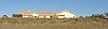
And here is the site. The array will be
oriented 0.57 degrees west of true south in order to best fit the support
posts to equal
elevations along the bank. |
 |
|
The final design of the photovoltaic generating plant is a
semi-fixed array with adjustable elevation. The support structure is made of galvanized pipe and
12 gauge galvanized steel channel struts. |
The Final Design
|
|
There are 18 bays of the structure, each
with an axle that supports a frame of four PV panels. The
frame in each bay is center mounted on a length of 2" pipe, which has
been placed over the horizontal "axle" of 1-1/2" pipe. The 2" pipe can roll around the
concentric 1-1/2" pipe allowing easy adjustment of the array's elevation angle. |
Front View Drawing
PDF copy
|
|
The elevation angle is
adjusted by loosening the pipe straps on the elevation braces
and rotating the support frames. The pipe straps, when loosened,
can slide along the length of the braces. The drawing shows solar elevation angles at noon for a specific day of each
month at this latitude. This information helps when making
declination adjustments. |
Side View Drawing
PDF copy
|
|
Application for the building permit, and
also for the net metering and interconnect agreement with San Diego Gas
and Electric, required a one-line electrical drawing of the
system. The string of four panels in each bay are series-wired with
extra flexible #6 conductors that carry a UL RHW-2 designation. I
investigated a variety of wire types
before making the final selection.
|
One Line Drawing
PDF copy
|
|
The San Diego county building department recently offered a
one-day seminar for their enforcement officials (inspectors) in which they
were trained to inspect photovoltaic installations. I quietly strolled into
this seminar, fully expecting to be thrown out. But no one
objected and I received my best training regarding application of the National
Electric Code to PV systems. |
|
|
One segment of the seminar focused on clues that identify the system builder as "untrained and inexperienced".
Most of these clues are
blatant violations to the NEC, such as use of incorrect wire types,
inadequate wire sizing, or improper grounding. This inspired me to
prepare a checklist that I presented at inspection time. It served
two purposes; to show the inspector that calculations were properly
done, and to promote the illusion that I was a trained and experienced PV
system builder. I think it worked! The inspector approved the system and took the checklist,
asking if
he could use it to develop an official checklist for inspecting PV
systems. |
|